
Important Sections from the Regulation
Turkey’s building earthquake regulations, officially known as “Principles for the Design of Buildings Under the Effect of Earthquakes”, were updated in 2018. In Chapter 10 of the latest updated version, basic rules for light steel structures were also defined.
The height limit of light steel structures is defined as BYS = 8. Therefore, the highest point of any light steel structure can be extended up to 10.5 m, depending on the earthquake design class. It is envisaged to use the equivalent earthquake load method in the calculation of earthquake loads and to take the natural vibration period as 0.2 seconds for the calculation of the elastic design spectral acceleration. The load-bearing system behavior coefficient R and the strength excess coefficient D are given as R = 3 or 4 and D = 2, respectively, depending on the coating material of the shear panels.
The common method is to create shear panels, where the clad wall panels show horizontal strength and the total resistance of the walls specified in any direction can be calculated. The contribution of panels with a width greater than 300 mm and a height-to-width ratio greater than 4 will be taken into account in the design.
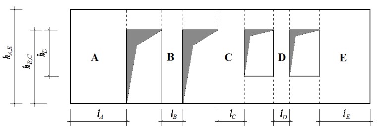
Figure 1. Constructing sliding panels. TDY 2018 Figure 10.7
Design with Safety Coefficients (GKT)” or “Design with Load and Strength Coefficients (YDKT)” can be selected as the design method. The total strength to be achieved will be reduced by using the relevant strength reduction factors. For GKT, Ω=2.5 and for YDKT, φ=0.6 will be taken. However, if the shear forces on the floors obtained by the equivalent earthquake load method are less than those obtained from wind effects, a shear panel will be created with the same method and Ω=2.0 and φ=0.65 will be used.
Recesses can be created on the facades of buildings. There are no requirements in our regulation regarding the layout of sliding panels, other than general irregularities in the plan. In such cases, article 10.2.2.2 of the regulation can be used. According to AISI S230, if the indentations are less than 1200 mm, it is assumed that the slip panels will show strength in a single direction.
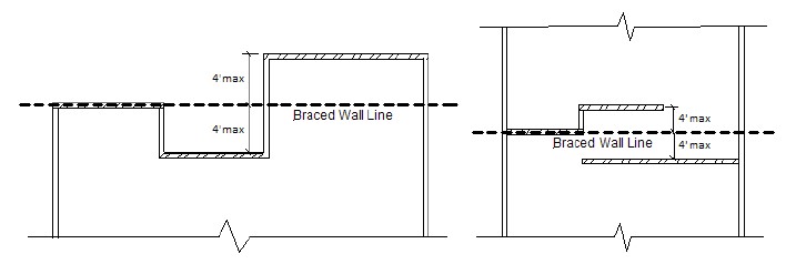
Figure 2. Linearity in shear panels. AISI S230-19 Figure E8-2
After selecting the placement of the sliding panels in the plan, detailing must be done. Table 10.5 in the regulation can be used for this. In this table, the spacing of the screws on the edge and inside, the coating materials and the approximate unit length strength can be seen. If there is no strength information obtained through physical testing according to the test conditions defined in Annex 10.C of the regulation, the strength of the slip panel constructed in accordance with the conditions defined in this section will need to be determined by experiments.
 by
by