
General
There are two types of trusses used in the cold-formed steel-framed construction business. One of them is the truss defined in AISI S240. These truss members are connected from the section’s webs. The second one is the connection from their flanges. The first type of truss is defined and guided at AISI. However, the other type of truss (in Figure 1) is not directly defined in any standard. Despite less guidance, flange trusses are widely used in the business.
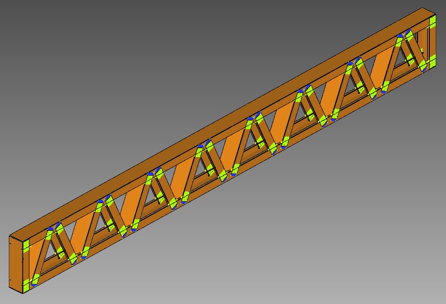 Figure 1. Flange Type Truss
Structural Models
Due to manufacturing techniques and narrow spaces in joints, eccentricities occur, and they create additional bending moments and second-order effects. AISI S240 does not specify the use of a multiple or single-node structural analysis model to account for the effects of eccentricity in joints. The truss stiffness will differ based on whether a multiple or single-node analysis is performed. Two different analytical models are illustrated in Figure 2.
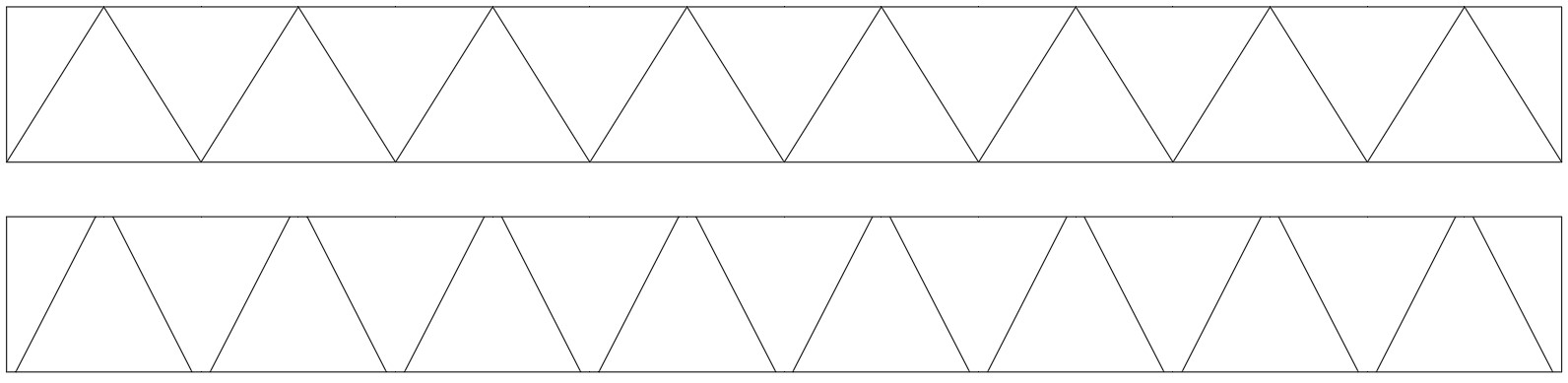 Figure 2. Single Node Truss and Two Node Truss
Based on a recent study on flange-type trusses by E.Baran and C.Dizdar shows that, this eccentricity decreases the truss stiffness. However, if four or more screws are used in the joints, there is not any significant difference observed in terms of stiffness at low-level loads. For example, the structural model may be constructed with a single node but it can be used at floor joists up to 5 or 6-meter clear spans in residential buildings. For complicated trusses in shape or long spans (6 m or more) should be evaluated with multiple node models.
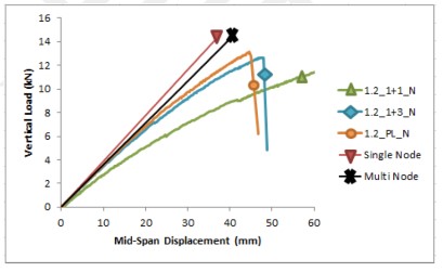 Figure 3. Flange Type Truss Test Results Using C Shape Thickness is 1.2 mm
Additionally, there is one more deformation in joints. Chord members are subjected to lip-cut in joints which removes the lip part of the section and diagonals can fit inside the chords. This operation, naturally, results in strength reduction in chord members. However, this operation is applied locally and creates a more complicated mechanism in connections. Strength check may be done using the formula AISI S100 H1-2-1 with chord member with lips by using a minimum of 4 screws. By using extra screws at unlipped chords, out-of-plane deformation of the chord flange is limited.
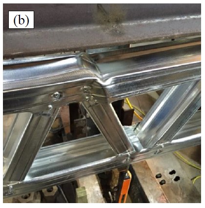 Figure 4. Extra Screw Effect on Ultimate Strength of Chord
 by
by