
Types of cold-formed steel sections
In the late 1980s’, researchers specified some critical conditions for the mass production of housing, and cold-formed steel sections have some vigorous properties to achieve these conditions [2].
- The construction components must be comparatively small, demountable, and as simple as possible.
- The network of lines and pipes must be very much independent of the other construction components.
A couple of construction methods are currently being used in the business, but the most common method is the stick-built method. In this method, the final assembly is done at the site. A sample wall assembly which tested in many aspects (structural, thermal, acoustic) by different researchers is illustrated in Figure 1 [3]. Vertical loads are carried through the floor joists and wall studs. Thin, relatively long steel sections are as much as simple and demountable, and mechanical system components run inside structural components independently.
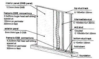
Figure 1. Sample wall assembly [3]
Cold-formed members and profiled sheets are steel products from coated or uncoated hot-rolled or cold-rolled flat strips or coils. They have a constant or variable cross-section within the acceptable range of tolerances. Cold-formed structural members can be classified into two groups. One is the individual members, such as studs, joists, etc. (Figure 2). Second, Panel and deck members (Figure 3) [1].
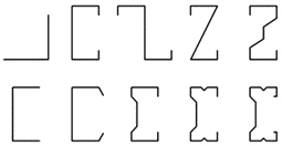
Figure 2. Typical cold-formed sections for individual members
Figure 3. Typical cold-formed sections for decking
In most applications, designers choose open-section, the heights from 50-70 mm to 350-400 mm with thicknesses from 0,7 mm to 6,0 mm. For decking, section thicknesses may decrease to 0,3 mm. Hybrid systems (combined with cold-formed steel members with hot-rolled steel sections) are also a practical option to overcome the problems resulting from structural system irregularities. However, if architectural plans, volumes, and dimensions are suitable, it is possible to design the whole structure without using any other structural element.
Cold-formed steel members are connected to each other with screws, rivets, and bolts. Due to its flexibility in use, it is simple to establish connections from every part of the section. Besides steel-to-steel connections, flat surfaces of steel sections are suitable for being connected to cladding material such as OSB and gypsum boards which provide significant stiffness [4].
In order to increase the stiffness of cold-formed sections and sheeting, edge and intermediate stiffeners are used. The stiffener of a cross-section means small bend parts of the flat part of the section [5].
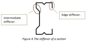
Figure 4. The stiffener of a section
Structural behavior
Cold-formed steel sections are generally thin, and portions of the sections are relatively long compared to their thickness. Thickness to portion length or portion’s width to length ratios is limited in the codes to use related formulas given in the code. However, if sections are physically tested, different ratios are allowed to be used [6].
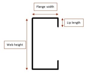
Figure 5. Typical open-section portions
Cross-section stability is a significant concern for cold-formed sections. These shapes may be considered “slender” or “non-compact” sections, meaning any fiber of the section may not reach yield strength under a specific loading before buckling locally or globally. Moreover, for thin-walled members, it is possible to see at least local buckling even if the section is fully braced against torsion or lateral displacement. Thus, buckling cases are paid special attention to in the design of thin-walled sections. There are a couple of buckling modes prevalent for thin-walled structures. Primarily, cases are local, distortional, and global buckling. For some exceptional cases, shear buckling, and web crippling should be evaluated for sectional stability [7].
Until the end of the 1970s,’ it is a standard calculation method to use Winter’s effective width method [8]. In 1978 Hancock [9][7] proposed using a signature curve, which illustrates the buckling modes related to member length. A graph is constructed with the calculation of the critical buckling stresses for each length. Minima of the graph define a specific buckling case. Primarily, larger parts of the section move out of the plane, and corners of the section stay (Point A in Fig. 6). When the length is increased, stress tends to increase and then decrease. The graph gives a minima for a certain length again, and distortional buckling occurs in the corresponding length. Generally, parts having stiffener, move out of the plane totally (Point B in Fig. 6). For larger lengths member is subjected to global buckling.
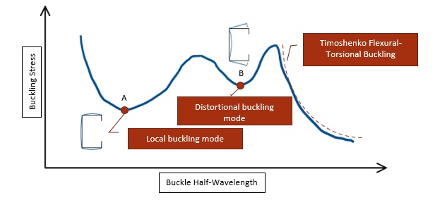
Figure 6. Typical Plot of a Signature Curve of a Thin-Walled Section
In common practice, members are connected to each other from their slender parts. As an example, C-shaped beams may be seated on a stiff member. In that case, web may be subjected to buckling locally which is called “Web crippling”. Web crippling may be a critical problem in cold-formed steel structures because this action creates soft and weak support for the member [1].
Studs and beams are usually used with holes on their web and flanges. The effects of holes for bolts and screws are minor but holes for the passage of utilities such as electrical, plumbing, or similar affect stiffness [10]. Because of the disturbance in the stress distribution on stress due to holes, openings can decrease or increase the critical buckling load depending on the half-wavelength and hole pattern [7].
References
[1] Dubina, D.; Ungureanu, V.; R. Landolfo (2012). Design of Cold-Formed Steel Structures, ECCS.
[2] Bats, J. O.; Janssen, J. F. G.; Industrial Housing with Cold-Formed Sheet-Steel Elements, in Proceedings of the 9th Int. Specialty Conference on Cold-Formed Structures. 1988.
[3] G. D. Corte; L. Fiorino; and R. Landolfo; Seismic Behavior of Sheathed Cold-Formed Structures: Numerical Study. 2006.
[4] Baran E, Alica C, Behavior of cold-formed steel wall panels under monotonic horizontal loading, Journal of Constructional Steel Research, Vol. 79, 2012, pp 1-8,
[5] Peköz, Teoman; Winter, George; and Desmond, T. P., “Edge Stiffeners for Cold-formed Steel Members”
(1978). International Specialty Conference on Cold-Formed Steel Structures. 6.
[6] EN 1993-1-3 (2006): Eurocode 3: Design of steel structures – Part 1-3: General rules – Supplementary rules for cold-formed members and sheeting.
[7] Adany S; Signature curve for general thin-walled members. Proceeding of the annual stability conference, Baltimore, Maryland, 2018.
[8] Winter, G.: “Light Gage (Thin-Walled) Steel Structures for Building in the U.S.A.,” preliminary publication, 4th Congress of the International Association for Bridge and Structural Engineering, 1952.
[9] Hancock, G.J. (1978), Local, Distortional, and lateral buckling of I-beams, ASCE Journal of structural engineering, 104(11), pp. 1787-1798.
[10] Moen, C.D., Schafer, B.W., 2009. Direct Strength Design of Cold-formed Steel Members with Perforations, Research Report. American Iron and Steel Institute (AISI), Washington, DC.
 by
by